Send me a message with your email when you get a chance, I can't remember if I have it or not.
There's a couple minor issues with this train of thought. Not that it is wrong, or shouldn't be pursued!
Using a CMM, since you have access to one, will be a great way to measure the back of the bolt lugs in reference to the bolt face, as well as the bolt handle. However, the bolt handle varies quite a bit. Additionally, the most important feature of the bolt handle, the extraction cam, wouldn't be measured in this way. The front face, and rear face, of the bolt handle are both "clearance" non contact surfaces.
Another issue will be wear and variance due to manufacturer and of course fitting. Just something to keep in mind.
I don't have a CMM, so when I reverse engineer parts, I typically make a spread sheet to try and find my nominal. Sometimes that is nearly impossible due to variance....
One would assume incorrectly that making the parts to the nominal of the drawing would be correct, but I have found on several occasions that is not the case.
Here is a copy of the content of the PM I sent you:
"Specific Questions:
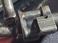
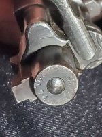
On the bolt handle in specific, aren't they welded in place with the seam machined flush? From the bolt I have at home(mauser standardmodell 1924 Ethiopian) it seems that the surface smoothness is sharply different where the handle meets the body, and the bluing is ever so slightly differently colored on either side which to me screams a different steel alloy or material condition. I might be wrong on this one, but it seems likely just based on efficiency of manufacture.
With the bolt handle and other camming surfaces, I had assumed that their profile was simply a mirror of the 40mm pitch camming surfaces present on the receiver body. Is this an incorrect conclusion? I still need to brush up on my GD&T, will have to figure out how camming surface tolerances are defined.
So far as I know, bolt bodies between 'mainline'(non M48) post-98 mausers are interchangeable entirely, even between the small and large ring rifles; is this not true? And further than this, while I know the M48 has some differences in the geometry of the feed ramp I don't know about the bolt body, are the bolts interchangeable. Of course, I when I say interchangeable I mean in terms of being used in M98 receivers, not in terms of bolt face differences when chambered for esoteric cartridges like 8.15x46R.
Manufacturer & Wear Variance: I'll go and read through the copy of
'The Mauser Bolt Action Shop Manual: M91-98' I managed to get my hands on to make sure I am not working on faulty information, but I remember that the bolts have a higher hardness than the receivers, and I cannot remember if that information is from that book or from somewhere else. If that is true, I would expect the issues from wear to be... well, not non-existent, but somewhat less of a problem than the issues from wear on the receiver. I remember the book having tolerances for the depth of the surface hardening layer on the receivers, but I don't remember if it did have the values for the bolts. Either way, what areas should I be most cautious of in terms of geometric or tolerance difference between the manufacturers? And which areas am I likely to see the greatest dimensional shift from wear? I already have the riding surfaces on the locking lugs earmarked.
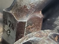
Current Plan: There is a store called 'Old Steel Historical Firearms' near me, and I know the owner and a few of the guys working there pretty well. I know they have, or had, a bunch of rifles imported from China which are an absolute dog's breakfast of different makers and years. I was thinking of going down and trying to buy four or five bolts, with the goal of selecting the ones that aren't just destroyed from extreme use or rust. Do you think that this would be a bad idea in terms of a source for measurement variance?"
On the bit you said about the nominal drawing being incorrect, I think the issue is that those drawings posted by Bruce don't have the manufacturing tolerances included. Now that I think about it, a somewhat less reliable way to go about the process of figuring out the above mentioned tolerances would be to use the fitment charts in the Machinery's Handbook.