Mauser K98 blueprints

Another situation where my lack of GD&T knowledge has bitten me, the method used in the documents is listed in your link.

A question for you. I have access to a lathe(with a four jaw chuck and the usual kit), verticle mill, and a hydraulic press. I recognized at the start of this project that the internal camming surfaces would need something weird to actually impliment, and with more knowledge I have come to the conclusion that I would need either a machine capable of live tooling or a shaper(though I am not sure how this would work, only that people recommended this method on a machinist's forum). My plan for this is to do some engineering to make a mini-shaper that grinds out the cam incrementally; however, on revisiting the documents I've realized that I overlooked the raceways in the receiver.

How would I do these without eliminating the bolt overtravel stops at the end of the receiver? The guide which started this project (linked here) uses ground down standard sized broaches to get them to near finished, then a file to get the final profile, however this method eliminates the overtravel stops as previously stated. The only tool that I can see being able to do this is a shaper, that is unless I include the idea into the 'mini-shaper' concept said previously.

I don't know. What is your take on it? Am I missing something that is obvious?

Either way, I need to revisit my kinematics
Apologies I missed this previously.

Will send you a PM.
 
Sorry, I forgot to add this update to the thread.
1743822762686.png
I have "finished" the receiver CAD and am now getting onto the bolt. I am about 80% sure it is accurate, but I have yet to go through validate it. The only parts I have left off the model are the edge breaking operations on the front of the 'rear bridge' besides the stripper clip guide, and the edge breaking operations on the side wall. Those features are monumentally awful to model and I don't particularly want to spare the brain power doing so.

On a separate note, do ya'll know about the thick side wall receivers? Specifically, how does the continuation of the front ring radius end/taper into the smaller radius that makes up the rest of the forging? I cannot find an image of an original thick wall receiver out of the stock.
 
Hello gentlemen.

Thank you for those pretty good drawings. Now I have decided to get involved in the work.

For now, I started with the barrel.

Screenshot (1912).png
 
Awesome work! Did you use the 8/3307A files as your reference? I hadn't even gotten a look at the barrel.
Hello sir.

I used the blueprints from the 4th page of the forum. Generally, I want to make both the gewehr 98 and the karabiner 98k. I think we can work together if you wish to.

With respect.
 
My request for PH 24/463 and PH 24/464 have come in. Both are digitized, the former contains info on the G98 and K98az stocks, the screws for securing the receiver to the stock/trigger guard, the (lange)P08's engineering drawings, and engineering drawings for the Hoffman Machine Pistol(MP18?), plus the snail drum, as well as some boxes and acceptance devices. I have not gotten to look through the latter, but I believe it is engineering drawings for acceptance devices and various components for the MG08, 08/15, and 08/17.

PH 24/463

PH24/464
 
Last edited:
My request for PH 24/463 and PH 24/464 have come in. Both are digitized, the former contains info on the G98 and K98az stocks, the screws for securing the receiver to the stock/trigger guard, the (lange)P08's engineering drawings, and engineering drawings for the Hoffman Machine Pistol(MP18?), plus the snail drum, as well as some boxes and acceptance devices. I have not gotten to look through the latter, but I believe it is engineering drawings for acceptance devices and various components for the MG08, 08/15, and 08/17.

PH 24/463

PH24/464
I found the book on internet,maybe some russian guy uploaded it,on the back section has completed drawings except leather holster and snail drum,just go through the book you may found the parts for the late production of the lange pistole,hopefully this will help you out.

Link Removed
 

Attachments

  • p08 8.png
    p08 8.png
    336.3 KB · Views: 28
  • p08 9.png
    p08 9.png
    335.3 KB · Views: 27
Last edited by a moderator:
I found the book on internet,maybe some russian guy uploaded it,on the back section has completed drawings except leather holster and snail drum,just go through the book you may found the parts for the late production of the lange pistole,hopefully this will help you out
Wow, nice work on the Lugers. Are your models dimensionally correct?
 
Last edited by a moderator:
I’ve removed the link to the copyrighted material - we can’t allow posting links to complete copyrighted books that don’t belong to us.
 
  • Sad
Reactions: JDS
Back in 2000 the company I worked for had a contract to do a complete 3D model of the Walther PPK/PPKS and to redo the prints. We modeled everything but the grips. The images are not the best quality but it's what I've got.

a PPK 1.jpga PPK 2.jpga PPK 3.jpga PPK 4.jpg
 
  • Like
Reactions: JDS
Wow, nice work on the Lugers. Are your models dimensionally correct?
Hello sir,I believe most of the parts are accurate,due to image quality,some of the measurements on blueprints are hard to read
and after finished all parts and found following:
1. large gap between rear bottom of the grips and lower frame,note,grip chequer pattern suppose engraved on both flat and curve surface.
2. unknown knurling on toggle,may be wrong pitch is used and only 3/4 straight knurling need to applied to toggle knob surface?

not sure if any special fitting process required during assembling to remedy those faults?
 

Attachments

  • 1..PNG
    1..PNG
    368 KB · Views: 14
  • 2.PNG
    2.PNG
    304.6 KB · Views: 14
Hi everyone,


I'm currently creating a 3D model of a milled Mauser K98k trigger guard, dated around 1940. My primary reference is the detailed technical drawing “RH 8/3307A – 0025.jpg” generously shared by“dder11”.


However, I’ve encountered a puzzling inconsistency. In the front view of the trigger guard , the area just beneath the receiver appears trapezoidal—wider at the bottom and narrower at the top. But in most real parts I’ve seen, as well as in other people's 3D drawings and photo references, that section is rectangular, with consistent width from top to bottom.


This small detail is driving me a little crazy (I'm a bit OCD when it comes to accuracy 😅
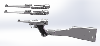
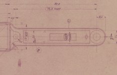
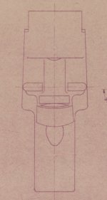
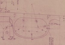
). I really want to model this part as precisely as possible.


Could this trapezoidal appearance be a result of the drawing perspective ? Or is there a legitimate variation in some early versions? I’d really appreciate any clarification or historical context you can share.


Many thanks in advance!
 

Attachments

  • Trigger Guard01.jpg
    Trigger Guard01.jpg
    109.4 KB · Views: 18
  • Trigger Guard02.jpg
    Trigger Guard02.jpg
    58.4 KB · Views: 18
  • Trigger Guard03.jpg
    Trigger Guard03.jpg
    121 KB · Views: 18
Last edited:
All bottom metal has what is called "draft" on the sides. If you have parts to handle in person, you can measure that they are in fact, not parallel walls.
 
Back
Top